Here in this article, I will explain all the steps that you need to follow if you want to make a 3DOF articulated robot. The steps include basics of the robot, mathematics of the robot that will include forward and inverse kinematics, simulations using MATLAB and RoboAnalyzer software then at last the Arduino UNO code for controlling the robot.
At the start of this mini project, I was doing guess in many things, so I will also mention what are the changes that I have done and why those changes are done.
 |
| 3DOF Articulated Robot |
 |
| Robot Progress (Idea to final product) |
3DOF robot CAD model:
My robot's name is Manas (मानस). Here you can see all the parts of the robot. I have used SolidWorks software for designing. The model reference is taken from grabcad and other websites. You can download the model also.
Manas: 3DOF Articulated Robot
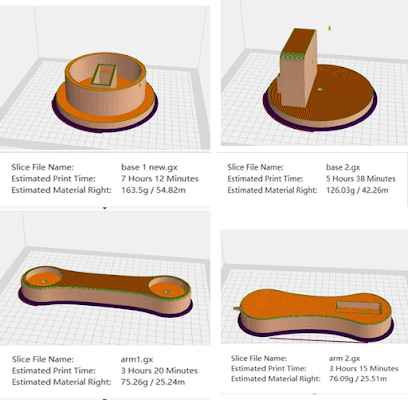
This is the model that I have made initially. I was thinking to make these parts by 3D printing but I came to the conclusion that 3D printing cost and timing will be very high for me. So, I dropped the idea of 3d printing and thought of making parts by CO2 laser cutting.
3D printing timing demonstration:
CAD model for CO2 laser cutting:
 |
| Arm2, Arm1, Servo2 Case, Base1, Base2: (Clockwise) |
 |
| Final Assembly |
Robot's 3 DOF Motion (updated parts)
Download CAD Model (Final): Click Here. (Base1 and 2 are of 5mm thick and rest are of 3 mm thick acrylic sheet)
Remember that I haven't made holes in robot parts for fabrication of servomotor. I done it separately by drilling. I have removed one of the servomotor cases in final assembly and used 4 L-shape metallic part to fix the servo2 case on base2. You also need to make holes (which I haven't made initially in CAD) for the L-shape metallic part.
It will be recommended to modify the parts in CAD and then do laser cutting else you need to do drilling later which will take extra time.
Note: If you don't have acrylic material, then you can make the parts by metallic sheet or wood. You can follow my dimensions.
CO2 laser cutting Process:
Convert the SolidWorks part as .DWF, this format will be used for laser cutting. Here this is the C02 laser cutting video. (Take care of dimensions while saving .DWF file, prefer mm). Some of the holes (for servo motors) I forgot to do so I have done drilling for it.
All robot parts (by laser Cutting)
Laser Cutting (Source: IIT P MICL)
Drilling for servo attachments (Source: IIT P)
Forward and Inverse Kinematics:
I have used this research paper to get idea of forward and inverse kinematics for a robotic arm. You can see my notes to get all basic idea of the matrices that are used in robotic calculations.
Mathematical Calculation: First of all, calculate the DH parameters of your robot. DH parameter is little hard to understand for the first time. These two videos will help you to understand the concept of DH parameters. Watch it
If still the concept is not clear to you then don't worry RoboAnalyzer(I have explained later in this article) will give you the DH parameter directly.
 |
| Source: RoboAnalyzer(IIT Delhi): Download |
Robot Arm Motion
If you have gone through my notes, then you have the idea of the transformation matrices. We are going to use it now to get the location of end effector and robotic arm angles.
Note: Some of the data and pictured are not of my robot. I have use it to explain the concept. You can click on the source link to see the actual source.
 |
| DH Parameter of my robot (Distance in cm and Angle in Degree) |
 |
DH Parameter
|

 |
x,y,z location of end effector |
What is forward kinematics: In very short, in the forward kinematics our input is the angles (of motor) and the output is motion and location of end effector. In robotics forward kinematics is not that much useful.
What is inverse kinematics: In real world application we know the location of end effector and we want to move it to a known location. It means we know the x, y coordinates. Now we need to know the angles θ1, θ2, θ3 and corresponding angular velocity to do the task. To get the angles we do inverse kinematics. Read this
paper (section 2.5)

Inverse Kinematics: Watch this
video.
Read my Notes on Inverse Kinematics: Download
RoboAnalyzer Software: This software helps you to understand DH parameter, forward and inverse kinematics, dynamic and many more this. Download it and make the simulation of your robot.
Click here
 |
| 3DOF arm simulation |
After finding DH parameter and inverse kinematics. We know that inverse kinematics gives multiple solutions, and all solutions are not feasible. I have limited the ranges of all the servo motor's angles based on the factor of safety. You need to do that too.
Then based on these angles, measure the workspace that is accessible by your robot's end effector. This data is for my case. Note that my robot can go far from this range, but I intentionally made the workspace smaller than the actual, for safety.
 |
| My Robot Workspace |
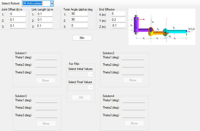
Now select a random point which is inside this workspace. Go to inverse kinematics tab of RoboAnalyzer software, re-enter all the data of your robot and run do the inverse kinematics.
 |
| Enter you robot data here and click on IKin |
 |
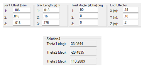
| Solution4 is feasible for my Robot |
I entered x=0.15, y=0.10 and z=0.2 (all in meters). I got two solutions out of which solution 4 is possible based on my angle limitation. Here -ve angle means the motor needs to rotate in counterclockwise. These angles will be the input to Arduino code.
Jugad to stop falling of Arm1 because of servo 3 weight:
I was facing an issue with the Art1 which was self-falling because of weight of servo3. For this I attached 2 rubber band so that both will help the arm not to fall.
Arduino Coding:
In this robot, Arduino will be the microcontroller. Based on desired location (x,y,z) we'll find the three angles that are θ1, θ2, θ3 and these will be the input to Arduino. Before you do Arduino coding you need to understand the basic programming of servo motors.
MG996R, MG995 and
SG90 are mostly used for robot making. Read about these then continue the article.
I am using
MG996R servo motor whose code explanation is already available on this website. This code is designed is such a way that the robot goes to a point and return back to its initial position which allow us to calculate the precision of the robotic arm. Follow the code link here you will get the Arduino code and C++ code which will help you to calculate the time (in milliseconds) that you need to enter in Arduino corresponding to the three angles.
Code link (Arduino and C++): shorturl.at/imnrQ . With this
C++ code you can find time corresponding to a particular angle.
 |
| Code for 90° CW then 90° CCW |
Code Explanation: (This is not full code)
Line 1 to 4, servo names are defined. This was a test code, and I was using it for only 1 servo motor that's why other two servos are commented out.
Line 6 to 11, Pin location of Arduino is mentioned.
Line 16, Delay of 3000ms (or 3 seconds) is given. Line 17,18 and 19 will on the motor in clockwise order and stop it after 748 milliseconds.
Line 23,24 and 25 will return the robot's end effector to its initial position.
For full code (all servo combined) and optimized algorithms. Visit my YouTube channel.
90° CW then 90° CCW (Code Output)
Code for all servo actuation (Non optimized)
Circuit Diagram and Power Supply:
Digital pin of Arduino is used. I have used 9,10 and 11 (signal wire of servo motor will be connected from Arduino). To power the servo motor, I used 6-volt power supply. Don't connect the servo motor directly to Arduino and Don't forget to connect the ground of 6-volt supply's ground to Arduino's ground. You can get wire connection or circuit diagram from google or YouTube.
 |
| Final robot with Fix base |
Any suggestion from you will be welcomed. I hope you have learnt something new and get some idea how to make a 3 degrees of freedom robotic arm. Do comment if you have any doubt. Have a good day.


